5
Thirty years ago, reviving a dead battery required little more than matching red to red, black to black, and revving the engine of whatever pickup truck was parked nearby. The vehicles of that era were forgiving. Simple analog relays, rugged mechanical distributors, and rudimentary fuel management systems absorbed electrical fluctuations with minimal protest.
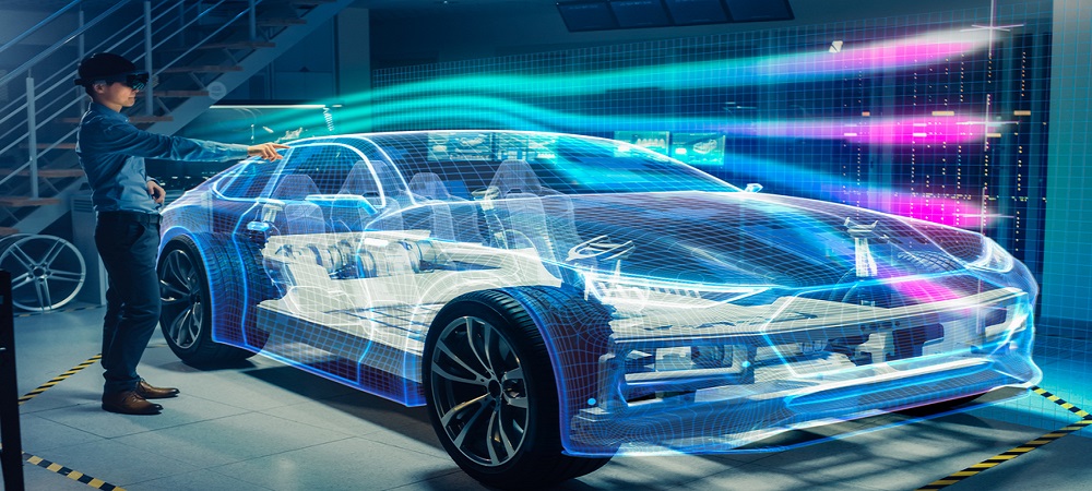
Today, the vehicle sitting in your driveway is essentially a high-performance server farm on wheels. A contemporary automobile integrates anywhere from 50 to 150 independent electronic control units (ECUs). These microprocessors govern everything from variable valve timing and transmission shift logic to adaptive cruise control, lane-keep assist cameras, and digital gauge clusters. They communicate continuously across sensitive Controller Area Network (CAN) and Local Interconnect Network (LIN) data buses that operate on precise voltage thresholds.
A sudden voltage transient during a poorly executed jump-start can send an uncontrolled electrical surge through that delicate architecture. In a fraction of a millisecond, an errant voltage spike can permanently puncture the microscopic silicon gates inside a powertrain control module or corrupt the body control computer, turning a routine roadside inconvenience into a four-figure repair bill. Bringing a dead vehicle back to life requires respecting the physics of modern automotive electronics and abandoning outdated habits.
The Anatomy of an Electrical Spike: Why Modern ECUs Are at Risk
To protect a vehicle’s circuitry, you must first understand what actually damages it. Batteries do not fry automotive computers; voltage spikes and uncontrolled inductive surges do.
When a battery dies, its internal resistance changes dramatically. Under normal operating conditions, a healthy 12-volt battery acts as a massive electrical capacitor and buffer. It dampens the electrical noise generated by the alternator, absorbs sudden spikes, and stabilizes the nominal 13.8 to 14.4 volts circulating through the vehicle while the engine runs. When that battery discharges deeply, it loses its ability to buffer the system effectively.
The primary hazard during a jump-start is inductive kickback. Whenever heavy electrical current flows through an inductive circuit—such as starter motor windings, thick copper jumper cables, or heavy-gauge vehicle harnesses—a magnetic field expands around the conductors. If that connection is abruptly made, broken, or interrupted by a slipping clamp, the magnetic field instantly collapses.
According to the laws of electromagnetic induction, a collapsing magnetic field forces a massive voltage surge backward into the circuit. A 12-volt line can instantaneously spike to 50, 80, or even 100 volts for a few microseconds. While vehicle modules feature built-in transient voltage suppression diodes, these safeguards are designed to dissipate minor ripples, not severe electrical back-surges caused by sloppy jump-starting techniques. When those protection diodes fail, the microprocessors behind them take the hit.
The Hidden Complexity: Sensors, AGM Batteries, and Remote Terminals
Automotive manufacturers have completely re-engineered under-hood electrical management over the last two decades. Treating a modern engine bay like an old car is where most mistakes happen.
The Intelligent Battery Sensor (IBS)
If you examine the negative battery terminal of almost any vehicle manufactured within the last fifteen years, you will rarely see a bare cable clamped directly to the lead post. Instead, you will find a small black box integrated into the terminal clamp. This is the Intelligent Battery Sensor.
The IBS contains a high-precision shunt resistor and an onboard microcontroller that continuously tracks battery state-of-charge, state-of-health, internal temperature, and cumulative amp-hours. It relays this data directly to the engine control module to regulate the alternator’s charging output dynamically.
If you clamp a negative jumper cable directly onto that negative terminal post, you force hundreds of cranking amps directly across the delicate IBS shunt circuitry. At best, you bypass the sensor and blind the vehicle’s charging computer, which will lead to erratic alternator charging and false dashboard warning lights. At worst, you weld the internal shunt and fry the sensor assembly on contact.
Remote Jump-Start Terminals
Weight distribution requirements, compact engine bays, and crash-safety engineering have pushed the 12-volt battery out of the engine compartment in millions of modern vehicles. In many European sedans, performance coupes, and modern crossovers, the battery sits beneath the trunk floorboard, hidden behind rear quarter panels, or buried under the front passenger seat.
Automakers recognize that drivers cannot easily access these locations during an emergency, so they engineer dedicated remote jump-start posts under the hood.
The positive terminal is housed under a bright red plastic flip cover, usually marked with a distinct plus sign. The negative connection is not a battery post at all; it is an unpainted, heavy-duty metal stud, hex bolt, or dedicated bracket mounted directly to the engine block, strut tower, or unpainted chassis rail. You should always use these dedicated remote posts when they are present. They are wired through heavy-gauge busbars specifically engineered to handle jump-starting loads without bypassing current monitors or exposing cabin wiring to excessive current.
Advanced Battery Chemistries
Modern stop-start systems rely on Absorbent Glass Mat (AGM) or Enhanced Flooded Batteries (EFB) rather than traditional flooded lead-acid batteries. AGM units use micro-glass fleeces saturated with electrolyte, allowing them to cycle deeply without shedding plate material.
However, AGM batteries are intolerant of excessive heat and aggressive overcharging. Subjecting an AGM battery to sudden, unregulated high-voltage surges from a donor vehicle can boil off electrolyte that cannot be replenished, permanently degrading its capacity.
Step-by-Step: The Safe Jump-Starting Procedure
When using a donor vehicle, executing the process with methodical discipline prevents sparks, short circuits, and harmful transients.
Step 1: Pre-Flight Preparation and Inspection
Park the donor vehicle close enough that the jumper cables have ample slack, but ensure the vehicles do not touch metal-to-metal. If the car bodies contact each other, you risk creating an accidental ground loop that bypasses safety fuses.
Turn off the ignitions in both vehicles and engage the parking brakes. Shift automatic transmissions into Park and manuals into Neutral.
Visually inspect the dead battery if it is accessible. If the battery casing is visibly swollen, cracked, or leaking fluid, do not attempt to jump-start it. A swollen case indicates frozen electrolyte or severe internal shorting; introducing external current can ignite residual hydrogen gas and cause a violent rupture.
Turn off every single electrical accessory in both vehicles. Switch off headlights, climate control blowers, heated seats, rear defrosters, infotainment screens, and radar detectors. Unplug smartphone chargers from 12-volt auxiliary sockets. You want the electrical bus on both vehicles entirely dormant before connecting external conductors.
Step 2: The Precision Connection Sequence
The order of connection is engineered to eliminate the possibility of a live tool or clamp accidentally grounding out against the chassis while completing the circuit.
First, connect the first red clamp to the positive terminal or dedicated remote positive jump post of the dead vehicle.
Second, connect the second red clamp to the positive terminal of the donor vehicle’s battery.
Third, connect the first black clamp to the negative terminal of the donor vehicle’s battery.
Fourth, connect the second black clamp to a clean, unpainted, solid metal component on the dead vehicle—such as an engine hoist bracket, a bare strut tower bolt, or the designated ground post. Position this ground connection as far away from the dead battery as the cables allow.
Making the final connection away from the battery ensures that the inevitable small spark that occurs as the circuit completes happens far from any combustible hydrogen gas venting from the battery casing. Furthermore, grounding to the chassis frame routes current through the vehicle’s standard grounding paths rather than directly through the sensitive Intelligent Battery Sensor.
Step 3: The Charge and Transfer Phase
Start the donor vehicle’s engine and let it run at a standard idle. Resist the common urge to rev the donor car’s engine aggressively. Modern alternators generate plenty of charging current at idle, and holding the donor engine at high RPM can introduce excessive alternator ripple voltage into the interconnected system.
Allow the donor car to run connected for five to ten minutes before touching the dead car’s ignition. This waiting period is critical. You are not simply using the donor vehicle’s starter circuit to turn over the dead engine; you are transferring surface charge into the dead battery. Letting the dead battery absorb electrical energy lowers its internal resistance and restores its ability to serve as a transient buffer before you crank the starter.
After several minutes, attempt to start the dead vehicle. Crank the engine for no more than five to seven seconds. If the engine catches, allow it to idle smoothly. If it does not start immediately, wait two minutes to let the starter motor cool down before attempting a second cycle.
Step 4: The Load-Dump Suppression Trick Before Disconnect
This is the single most important step for protecting delicate electronics, yet it is almost universally overlooked by roadside motorists.
Once the previously dead vehicle is running under its own power, both its alternator and the donor car’s alternator are actively producing current. If you immediately yank the jumper cables away, the sudden, instantaneous removal of the external load can trigger an alternator load dump spike, hitting the microprocessors with a sudden voltage crest.
To neutralize this risk, walk over to the newly revived vehicle and switch on the rear window defroster and the cabin HVAC blower motor on medium speed.
Do not turn on headlights, which contain expensive HID ballasts or LED control drivers. The rear defroster grid and blower fan are heavy, purely resistive electrical loads. They act as heavy electrical sponges. Any transient voltage spike produced when the jumper cables are severed is immediately absorbed and dissipated by these robust resistive elements, completely insulating the delicate digital control units.
Step 5: The Safe Disconnection Sequence
With the resistive loads running, remove the cables in the exact reverse order:
First, disconnect the black clamp from the chassis ground of the newly started vehicle.
Second, disconnect the black clamp from the donor vehicle’s negative terminal.
Third, disconnect the red clamp from the donor vehicle’s positive terminal.
Finally, disconnect the red clamp from the newly started vehicle’s positive terminal.
Once the cables are stowed safely away from moving engine belts and cooling fans, switch off the rear defroster and let the vehicle run for at least twenty to thirty minutes of active driving to allow the alternator to replenish the battery’s operating reserve.
Dedicated Lithium Jump Packs vs. Donor Vehicles
While using a donor vehicle remains a viable emergency technique, modern portable lithium jump starters represent a massive leap forward in both safety and convenience for contemporary car owners.
A quality lithium jump pack (typically powered by Lithium Iron Phosphate or high-discharge Lithium Polymer cells) is fundamentally safer for modern electronics than jumping from another car. When using a donor vehicle, you are tethering two complex, active electrical systems together, each with its own alternator, voltage regulator, and varying load conditions. Fluctuations in one system directly impact the other.
A portable jump pack, by contrast, operates as an isolated, DC-only power supply. Reputable jump packs include integrated smart clamps fitted with microcontrollers that provide built-in safeguards:
Reverse-polarity protection physically prevents current from flowing if you accidentally cross the red and black leads, eliminating the catastrophic dead shorts that melt harness wires.
Anti-spark technology keeps the output clamps electrically dead until the onboard sensor detects correct attachment to a recognized 12-volt battery terminal.
Over-voltage clamping ensures the output voltage stays tightly capped between 12 and 14.8 volts, making it physically impossible for the unit to induce a high-voltage transient spike into the vehicle’s ECUs.
When using a lithium jump pack, ensure the unit has at least fifty percent state-of-charge before attempting a jump. Connect the clamps firmly, turn on the jump pack’s power switch (or wait for the solid green “ready” light on the smart box), and crank the vehicle. Once running, disconnect the pack within thirty seconds to prevent the vehicle’s alternator from back-feeding high charging current into the lithium pack cells.
Special Considerations for Hybrids and Electric Vehicles
The proliferation of hybrid electric vehicles (HEVs) and fully electric vehicles (EVs) has introduced widespread confusion regarding roadside jumping.
An electric car or conventional hybrid still uses a standard 12-volt auxiliary battery alongside its massive high-voltage (300V to 800V) traction battery pack. The high-voltage pack is completely isolated while the car is parked. The 12-volt battery is what powers the central computer, boots up the vehicle operating system, and trips the high-voltage relays (contactors) that connect the big battery pack to the drivetrain when you push the start button.
If the 12-volt auxiliary battery in an EV or hybrid goes completely dead, the car will not start, despite having a massive, fully charged traction battery sitting beneath the floor.
Can You Jump-Start a Dead EV or Hybrid?
Yes. You can jump-start the 12-volt auxiliary system of an EV or hybrid just like an ordinary car. In fact, it requires far less energy because there is no mechanical starter motor to crank. The jumper cables only need to deliver enough power to boot the vehicle’s control modules and close the high-voltage contactors. Once those contactors snap shut, the onboard DC-to-DC converter takes over and begins powering the 12-volt bus from the main traction battery.
Can an EV or Hybrid Act as the Donor Car?
In almost all cases, absolutely not. You should never use an EV or a hybrid to jump-start a conventional gas or diesel vehicle.
Combustion engine starters draw massive initial inrush currents, routinely demanding between 300 and 600 amps to spin a cold engine block. Hybrids and EVs do not have traditional mechanical alternators; they use solid-state DC-to-DC converters to step high traction voltage down to 12 volts.
These converters are strictly rated for continuous auxiliary loads, typically between 100 and 150 amps total. Forcing an EV’s 12-volt system to support the massive cranking surge of an external gas engine can overwhelm and destroy the DC-to-DC converter. Replacing that converter module is an extraordinarily labor-intensive repair that routinely costs thousands of dollars. Unless your specific owner’s manual explicitly outlines a procedure for donor jumping, keep your EV or hybrid out of the donor role.
What to Do If the Vehicle Still Fails to Start
If a vehicle refuses to start after a proper ten-minute charging window, forcing continuous cranking will only damage the starter motor and overheat the cables.
Modern vehicles employ aggressive low-voltage cutoffs. If the vehicle’s central computer detects system voltage dropping below approximately 10.5 volts during cranking, it will intentionally shut down the fuel injector drivers and ignition coils to prevent memory corruption. The starter might still spin the engine weakly, but the engine control module will refuse to fire. In this scenario, the battery’s internal plates have sulfated to the point where the unit can no longer sustain voltage under load, and a replacement battery is the only solution.
Keep in mind that on many modern luxury and technology-heavy vehicles, simply dropping in a new battery is not the final step. These cars require battery registration using an OBD-II diagnostic scan tool. Registration resets the charging algorithm inside the engine computer, informing the alternator that a new battery with fresh internal resistance has been installed. Without registration, the computer will continue charging the new battery using the aggressive, high-voltage profile it developed to compensate for the old, dying unit, cutting the lifespan of the replacement battery in half within months.
Treating your vehicle’s electrical system with precision transforms a stressful roadside failure into a controlled mechanical task, keeping every computer on board protected.
